
Industry News
Achieving Disc Cutting Precision: A Technical Guide to Spindle Stability and Slicing Accuracy
In high-precision manufacturing sectors—ranging from semiconductor wafer dicing to the production of ultra-thin optical glass and hardened alloy shims—Disc Cutting Precision has transitioned from a quality metric to a fundamental necessity. As industries push toward sub-micron tolerances, the mechanical behavior of the cutting system under high-speed rotation determines not only the yield rate but the structural integrity of the final component.
Achieving superior Disc Cutting Precision requires an analytical approach to the machine’s dynamic architecture. It is no longer sufficient to focus solely on the blade’s sharpness; engineers must now account for the complex interplay between spindle kinematics, thermal drift, and the vibration damping capacity of the entire assembly.
Defining the Parameters of Disc Cutting Precision
In the context of industrial slicing, precision is a multi-dimensional concept. It encompasses dimensional tolerance, parallelism of the cut faces, and the micro-topography of the kerf. The primary driver of these outcomes is the spindle system.
The mechanical rigidity of the spindle dictates how the tool behaves at the moment of impact with the workpiece. If the spindle stability is compromised, even by a magnitude of two micrometers, the resulting harmonic vibrations will manifest as visible “chatter marks” on the cut surface. For high-speed applications exceeding 30,000 RPM, the system must maintain its geometric center while subjected to significant radial and axial loads. This stability is the physical foundation upon which all Disc Cutting Precision is built.
The Impact of Spindle Runout on Surface Parallelism
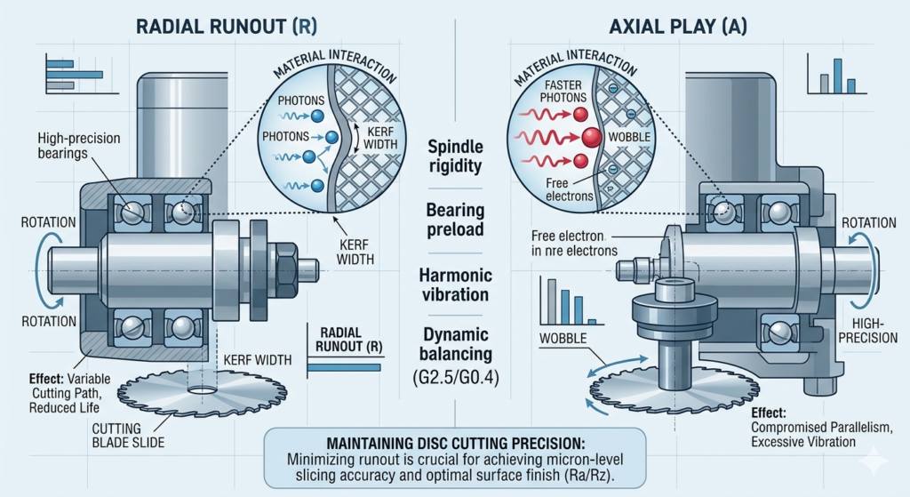
To optimize Disc Cutting Precision, one must differentiate between radial runout and axial play. Radial runout—the deviation of the spindle’s rotation from its theoretical axis—leads to inaccuracies in the kerf width and can cause premature blade wear. However, for thin-disc slicing, axial play is often the more destructive force.
Axial displacement during rotation causes the blade to “wobble” sideways. This wobble directly compromises the parallelism of the sliced part. When aiming for micron-level metal slicing accuracy, the use of high-precision angular contact ball bearings or air bearings becomes mandatory. According to technical documentation from SKF, the running accuracy of a spindle is heavily influenced by the internal preload and the thermal stability of the bearing arrangement.
Balancing Requirements: The ISO 1940 Standard
A critical, yet often overlooked, component of Disc Cutting Precision is the dynamic balance of the rotating assembly. At high velocities, any residual unbalance generates centrifugal forces that increase exponentially with speed ($F = m \cdot r \cdot \omega^2$).
Adhering to the ISO 1940-1 standard is essential for any facility targeting high-tier industrial markets. For precision slicing, a balance grade of G2.5 or G0.4 is typically required. Maintaining a G2.5 balance grade for spindle life ensures that vibration amplitudes remain below the threshold that would interfere with the cutting path. Without proper balancing, the spindle effectively becomes a vibration generator, systematically destroying the Disc Cutting Precision that the rest of the machine is designed to provide.
Technical Reference: ISO 1940-1:2003 – Mechanical vibration — Balance quality requirements for rotors.
Thermal Displacement and Micron-Level Drift
During extended production cycles, heat generation within the spindle motor and bearings causes linear expansion of the shaft. This thermal drift can shift the tool’s position by several microns over the course of an hour, silently eroding the Disc Cutting Precision established at the start of the shift.
Advanced manufacturers mitigate this by utilizing liquid-cooled spindles or shafts constructed from specialized alloys with low thermal expansion coefficients. Managing thermal displacement is not merely a maintenance task; it is a core strategy for achieving Micron-level metal slicing accuracy in 24/7 manufacturing environments. When the temperature fluctuates, the vibration damping capacity of the machine frame also changes, further complicating the precision matrix.
Practical Steps: How to Reduce Spindle Runout in Disc Cutting
To rectify precision issues on the factory floor, a systematic troubleshooting protocol is required. To improve your Disc Cutting Precision, implement the following technical steps:
1.Dynamic Runout Mapping: Use non-contact capacitive sensors or laser interferometers to measure runout at operational speeds, not just at rest.
2.Flange Interface Inspection: Ensure the tool-holding flange is free of micron-scale debris. A single particle of dust can create a leverage effect, magnifying runout at the blade’s edge.
3.Bearing Preload Calibration: Verify that the spindle bearings are preloaded according to the manufacturer’s specifications to prevent axial wandering.
4.In-Situ Balancing: Perform final balancing of the spindle with the cutting blade attached to account for the entire rotating mass.
Focusing on these mechanical interfaces is the only way to move toward achieving sub-micron tolerance in thin disc slicing.
Surface Integrity: Ra/Rz and Slicing Accuracy
The final evidence of Disc Cutting Precision is found in the surface roughness (Ra/Rz). Surface finish is a direct reflection of the micro-stability of the cut. If the spindle exhibits even minor instability, the frequency will be recorded on the material surface as a periodic wave pattern.
Troubleshooting surface waviness in high-speed disc cutting requires an analysis of the “System Stiffness.” If the cutting force exceeds the instantaneous rigidity of the spindle, the tool will deflect, creating a microscopic “climb” and “drop” effect. This not only ruins the finish but also compromises the volumetric accuracy of the part.
The Economic Value of High-Precision Slicing
Investing in Disc Cutting Precision is an economic decision as much as a technical one. In industries where raw materials—such as monocrystalline silicon or rare earth magnets—are extremely expensive, reducing the kerf loss by even 10 microns can result in significant annual savings.
Furthermore, high-precision slicing eliminates the need for secondary grinding or lapping processes. By achieving the target dimensions directly from the cut, manufacturers reduce cycle times and energy consumption. Therefore, the pursuit of Disc Cutting Precision is a pursuit of lean manufacturing efficiency.
Conclusion
Ultimately, maintaining Disc Cutting Precision is a continuous process of monitoring and adjustment. It requires a deep understanding of Spindle stability, a commitment to ISO 1940 balancing standards, and a rigorous approach to mechanical maintenance.
For the modern engineer, the goal is clear: transform the cutting process from a source of variability into a source of competitive advantage. By mastering the variables that govern Disc Cutting Precision, manufacturers can meet the most stringent global standards and deliver products that define the leading edge of industrial capability.
FAQ
How does spindle runout affect the life of the cutting disc?
Spindle runout creates uneven loading on the disc’s edge. This leads to localized overheating and “chipping,” which shortens tool life and significantly degrades the Disc
Is a G2.5 balance grade sufficient for all applications?
While G2.5 is the industrial standard, ultra-precision applications (like semiconductor dicing) often require G0.4 to minimize vibration-induced surface defects.